install.wled.me
A few months ago we - the puppet team (TM) - joined the fablab neukölln art makerthon. We had 48 hours to make something that should fit in a specified round frame and that we could showcase afterwards.
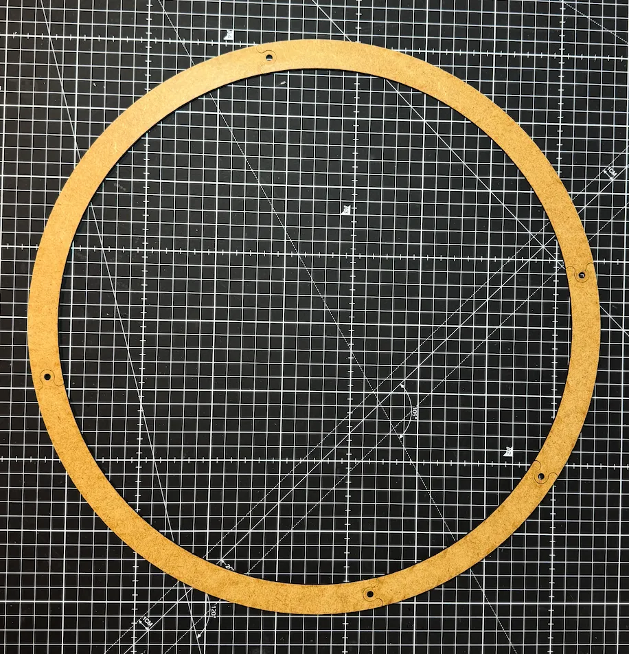
The frame we were given
flo-bit is a sucker for anything made with controllable RGB LEDs and he can be very convincing when he’s passionate (and what could possibly worth more passion than individually controllable RGB LEDs?).
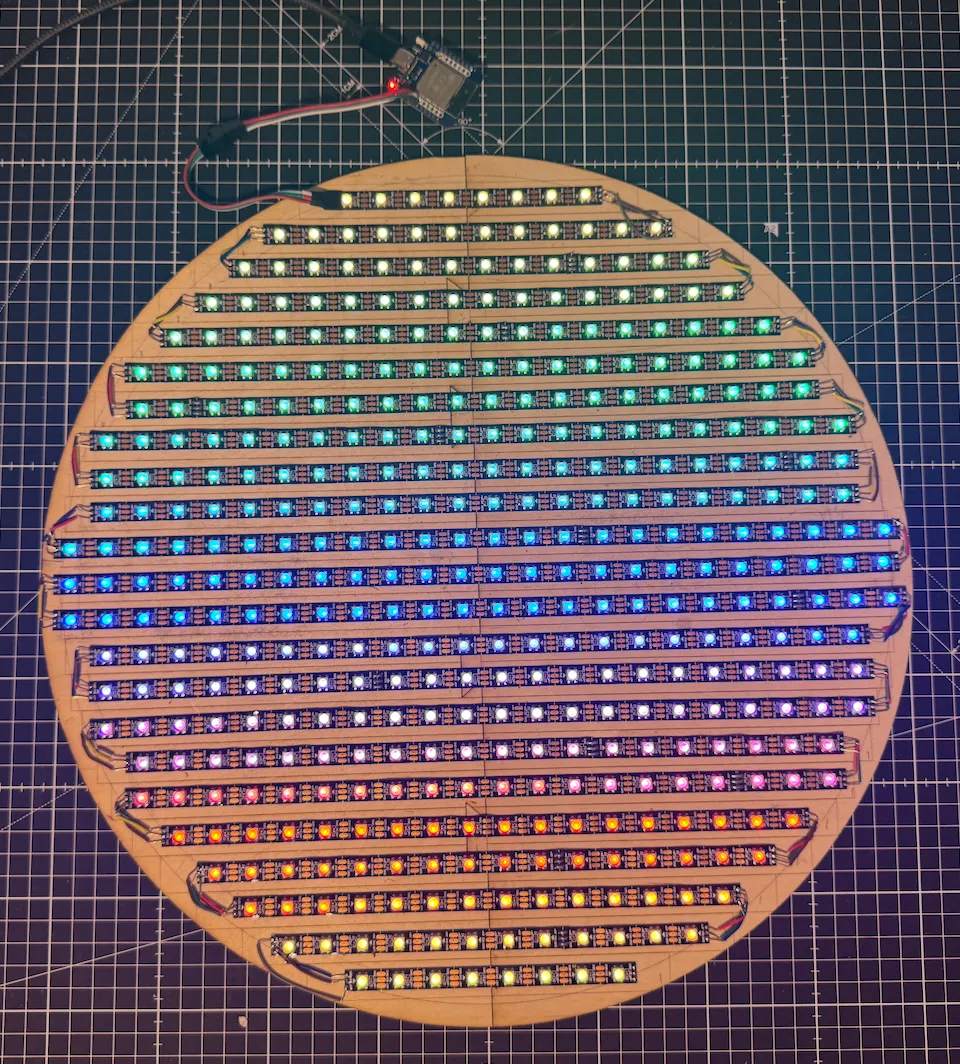
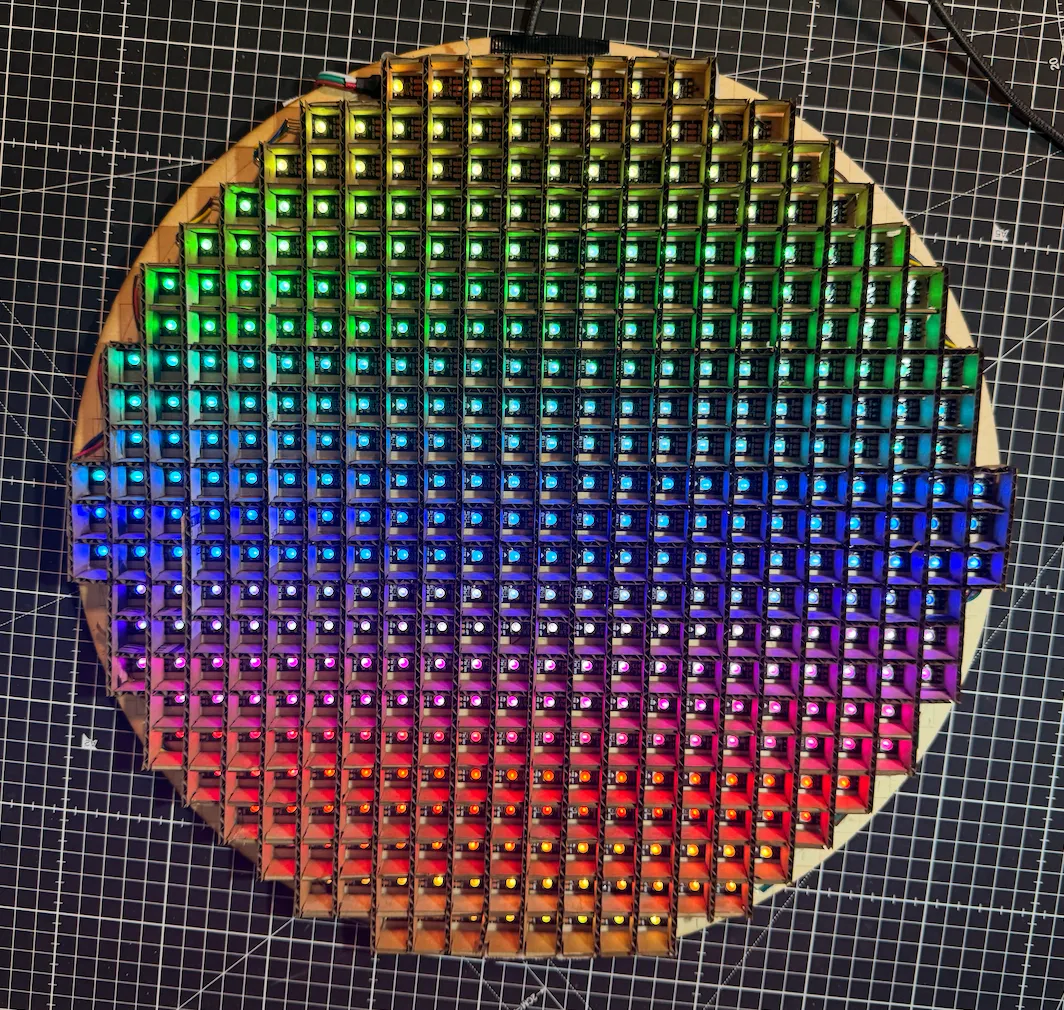
So we basically just put a bunch of LEDs into that frame and made a round display.
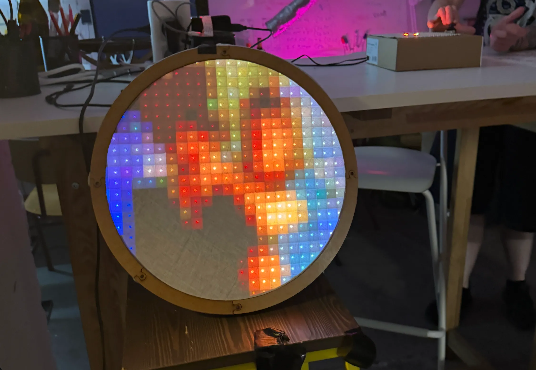
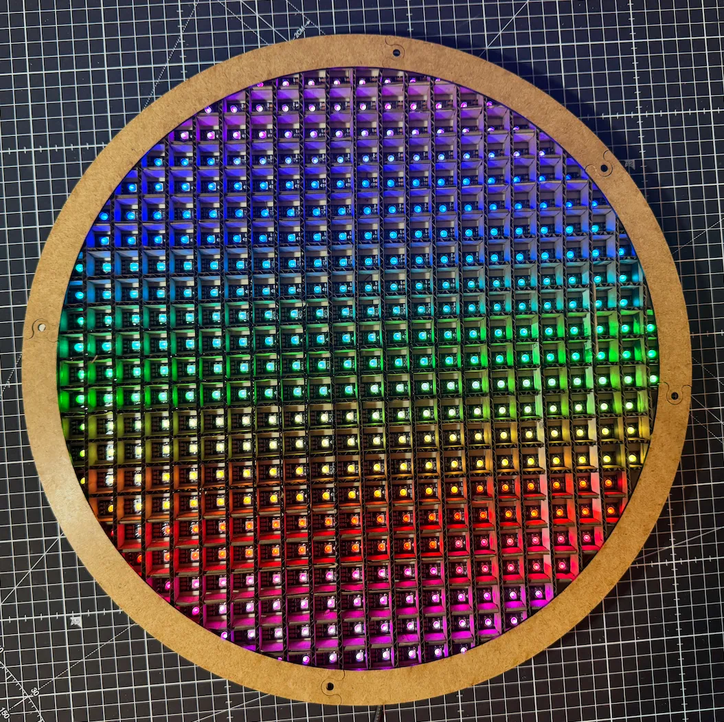
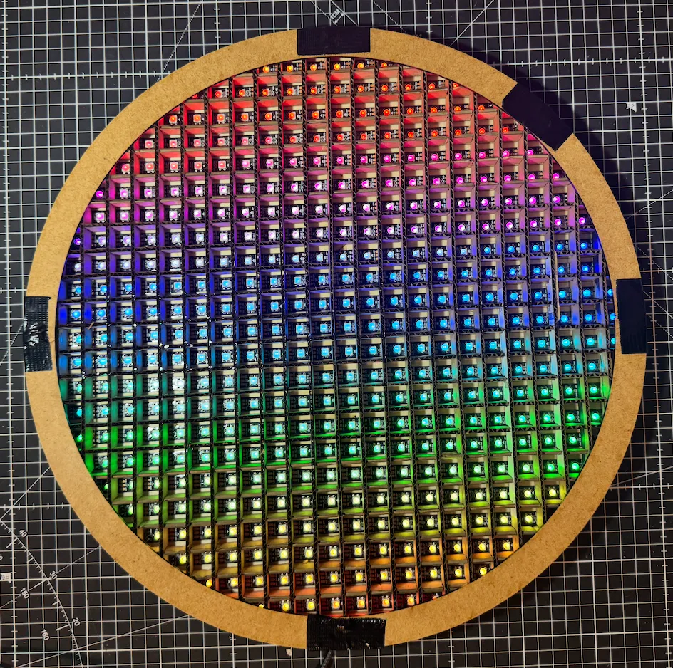
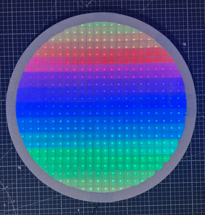
Here are a few of the cool effects it can show, curtesy of WLED.
This blog post is both the story of how we made it, as well as a how-to guide if you wanna make your own.
We did initially plan to have this work together with a camera and be a “pixel art” mirror and while we did get this kinda working for the demo, for the how-to we’ll concentrate on how to make the LED frame with just the effects above (so without the mirror functionality), as the mirror part is honestly very hacky and doesn’t even look that good imo.
If you plan to try your hand at making one, you need two things apart from the materials:
A solder iron (some experience with soldering might be useful, but this is also a good learning project, we don’t really know how to solder either, we just do it and sometimes it works 😝)
A laser cutter that has a cutting area of at least 40cm x 24cm, if you don’t have one, check your nearest makerspace
For the materials you need: (without the mirror functionality, for that you’d also need a raspberry 3b or above with wifi and a camera).
(links are to the german amazon, those are not referrer links, just where we bought stuff)
The main cost are the LED strips, we bought them from amazon for 15 € for 5 meters (so 7 meters are ~21 €). There are cheaper options available on something like aliexpress though.
An esp32 costs about 7 € (again less on aliexpress) and the wood we used was about 8 € for the 3 plates.
Everything else we had at home, but should be pretty cheap anyway (less than 5 €, if you don’t add a powerbank).
First we created the backframe, by lasercutting 2 of the plywood plates. Here are the files both for LightBurn and as SVGs:
Note that there are 2 layers, the first should be cut, the second is just for marking the LED strip positions (so use low power for that one).
The rings for the front were given to us already laser cut, but here are the files for anyone following along at home (from this fablab github repo). Use the last plywood plate to cut out the ring segments.
Use some wood glue or just duct tape to glue the parts together and you should have two rings and one big circle with markings on one side for the LEDs (you might be able to guess wether we used wood glue or duct tape…)
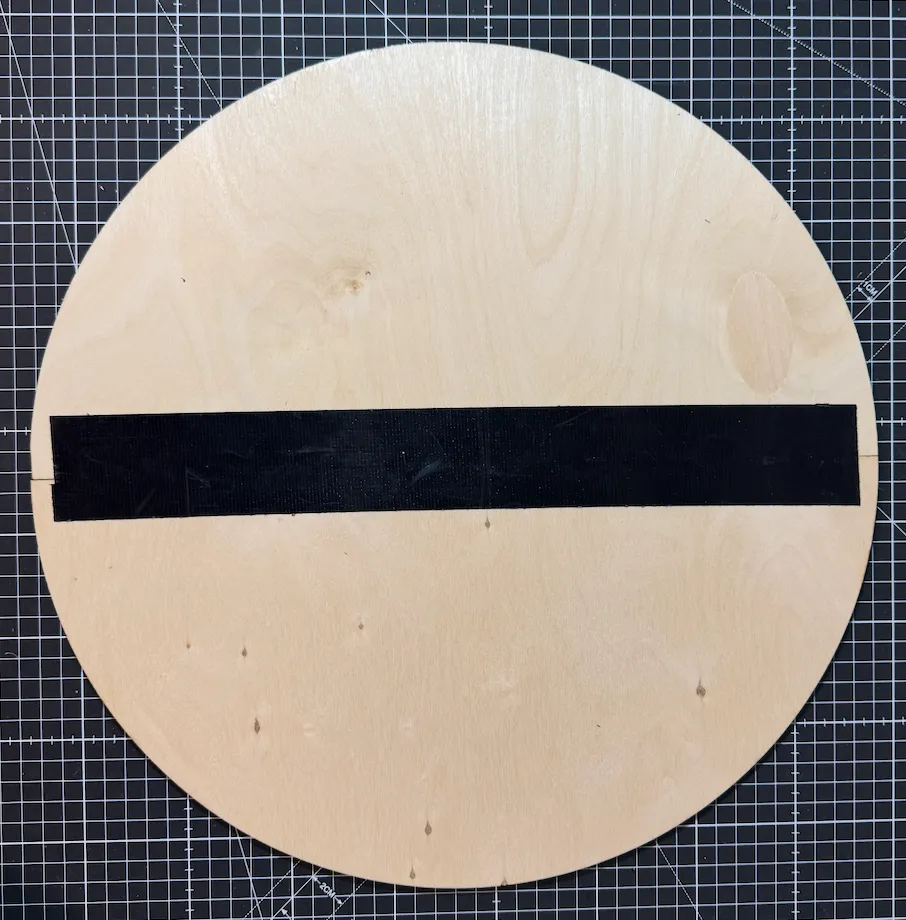
The backside of the base plate.
The walls are also lasercut but out of cardboard (would have taken way to long to cut them out of wood and we were in a hurry, you can cut them out of plywood too, but in the end they wont be visible anyway). We just used random packaging cardboard we had laying around.
Afterwards you can lay them on your base board (good luck figuring out which go where, we don’t have a good tip here, we struggled with that too 🙃) and start putting them together, we tried that without glue first, but after everything fell apart twice we went for some glue.
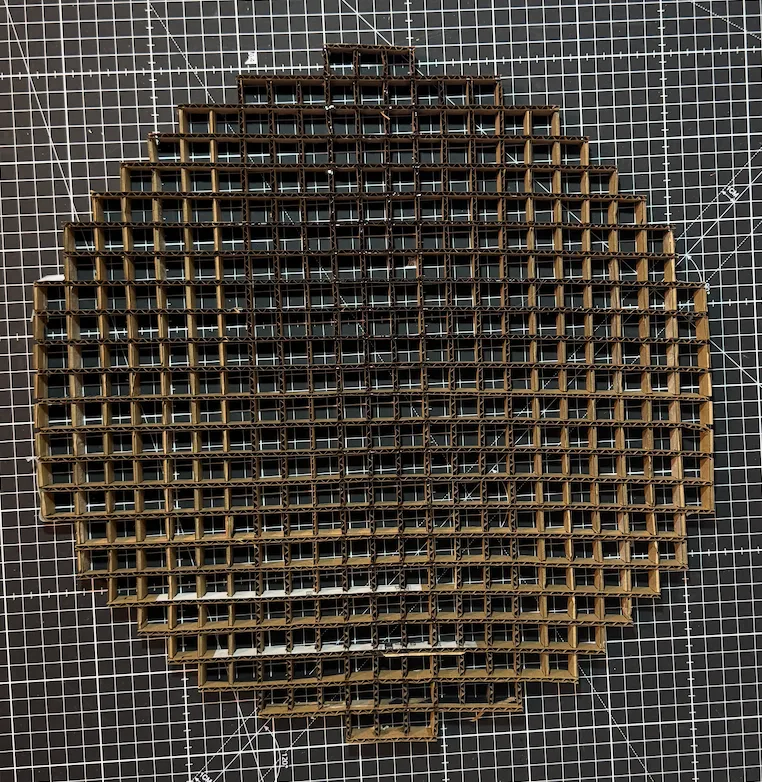
The cardboard grid.
Now for the first of three steps where you have to pay attention not to fuck it up: Cutting the LED strips into segments in with the correct amount of LEDs for each segment.
When cutting also make sure LED strips are cut exactly in the middle of a connection (so you have enough place to solder on both parts).
In total you need:
You can also directly lay them on the board (don’t glue them yet though) to make sure you have the correct count, they should fit perfectly in the little markings on the plate (lengthwise, they are less wide than the markings)
the LED strips have to be laid out in a serpentine arrangement with the correct count.
there are little arrows on the LED strips that show you the direction there are going, those should alternate go left to right then right to left.
Again pay lots of attention here, you can accidentially fry your LED strips if you make a mistake here (we’ve of course never fried any LED strip cough, cough, thankfully the LED strips are usually sold as 5 meter strips so you have some leftover)
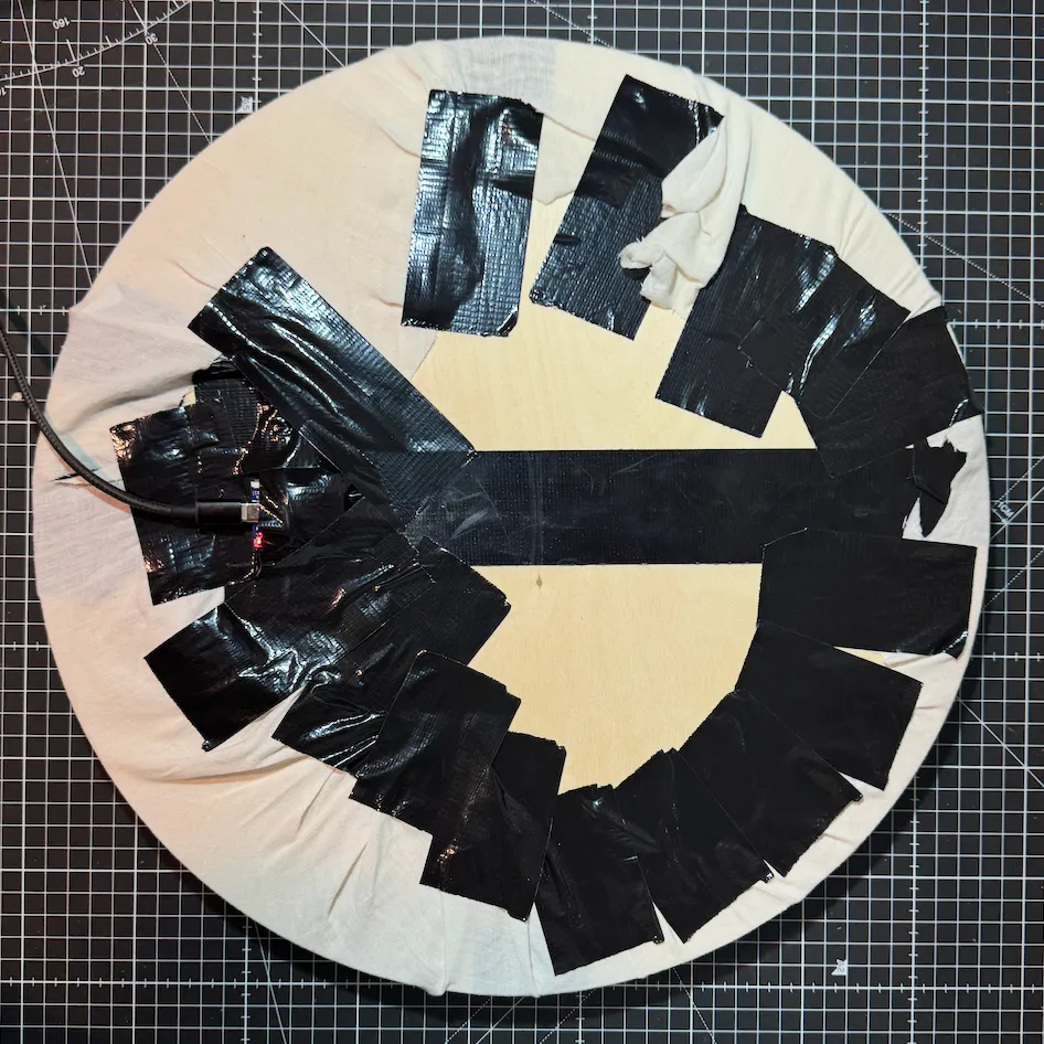
On each LED strip connection, solder together the 5V, ground and data connection like so:
In the end you should have something like this:
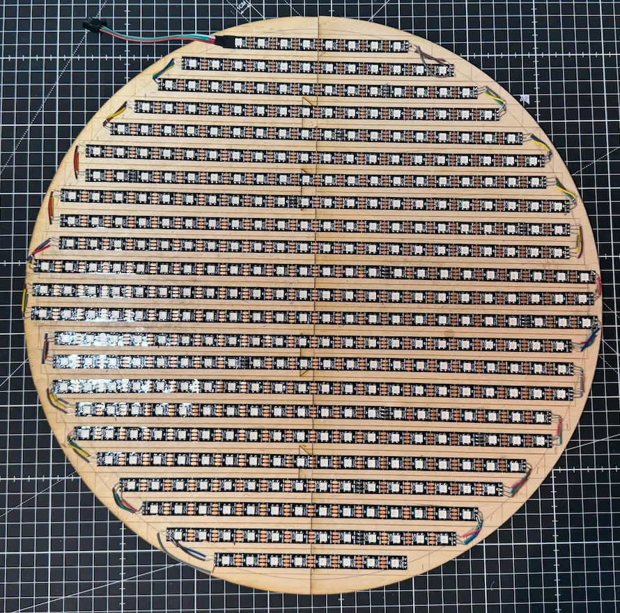
Professionally soldered I would say
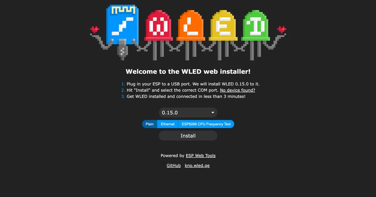
Take your esp32 and connect it to your computer (be sure to use a cable that has a data connection) and open this website:
install.wled.me
Click on install, select your usb port, confirm and wait a few minutes until it’s installed.
Once it’s done you’ll be asked to enter your Wifi credentials, do that and then click “Open WLED”. You should see a screen like this:
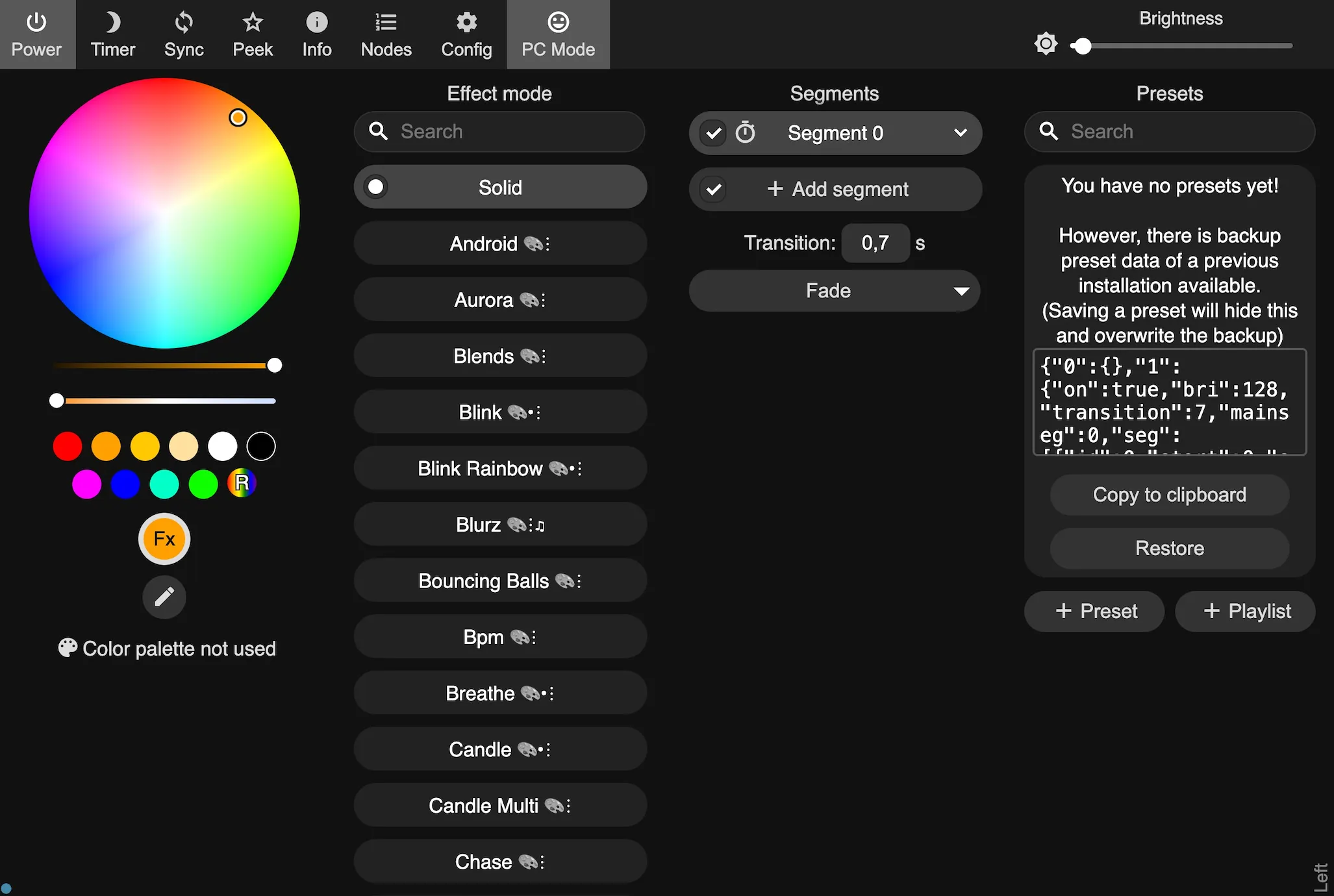
Main WLED screen.
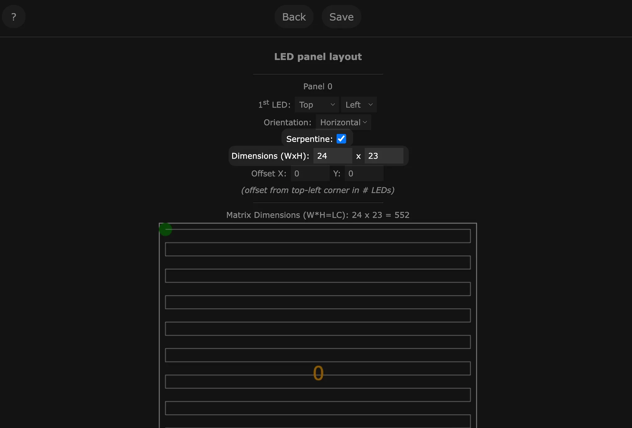
Click “Config” in the top bar to open the settings page, there click on “2D configuration”:
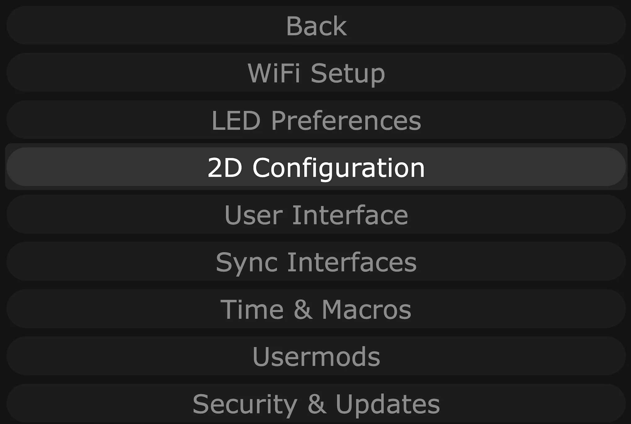
WLED settings screen.
Check serpentine and enter the dimensions as 24 by 23 LEDs.
WLED matrix screen.
Scroll all the way down and upload this gaps.json file:
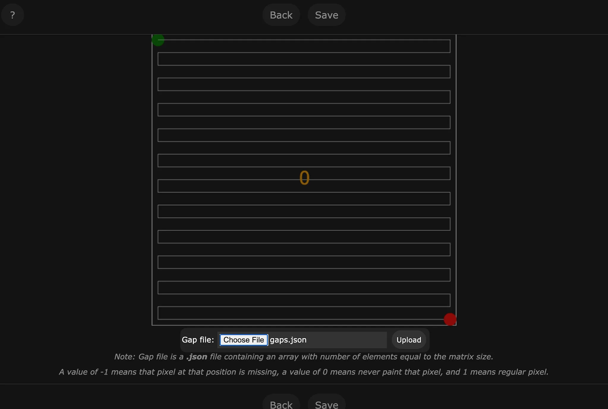
Select gaps.json file and click upload
Optionally go back to the main page and select a different effect (e.g. rainbow).
Last soldering part: solder VCC, ground and GPIO4 to the beginning of the first LED strip (GPIO4 goes to data, VCC to 5V and ground to ground, optionally you can use the 3 pin connectors that are usually part of the LED strips).
We did actually end up using the 3 pin connectors here.
Ok, we’re almost done, lets put everything together:
Put the grid on top of the base plate, aligning it with the LEDs.
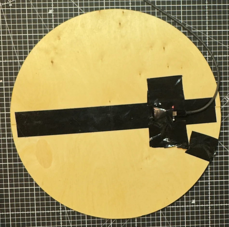
Optional step: We duct taped the esp32 to the back…
Put the first ring on top of the grid…
… and duct tape it to the back
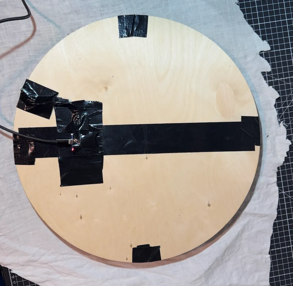
Flip the whole thing around and lay it on top of your fabric.
and more duct tape: Tape the fabric to the backside as well.

Who cares what the backside looks like…
Flip it around again and glue the second frame on top of the fabric.
We somehow forgot to take a picture of that last step, but we’re basically done, so it should look something like this:
So beautiful… This actually shows the “mirror” functionality too, pictured are flo-bit and polijn